A Minimum Space Elevator and Storage Sidings
By Robert Smith and Lyn Jones
Content
- Background
- Elevator Design
- Transmission System
- Drive System
- Alignment and Locking
- Vertical Positioning
- Electrical Interlocking
- Operation
- Conclusion
- Photographs
This article describes the background, design, construction and operation of an ‘O’ gauge traverser operating in a vertical plane in order to save valuable space. As such it should be of interest to many modellers who wish to reduce the space required for ‘off-scene’ operations and extend the scenic areas of their layouts.
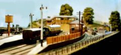
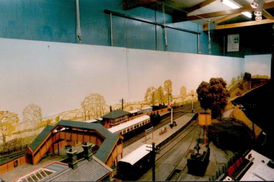
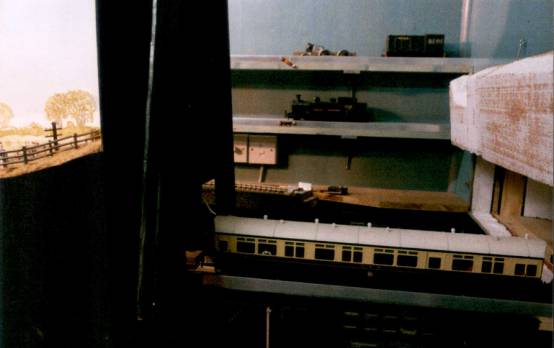
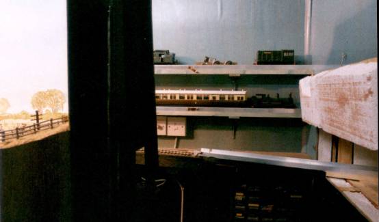
Elevator at lower level (left) and middle level (right), storage sidings in the background, loco storage in the right-foreground
1. Background
A house-move five years ago resulted in my ‘O’ gauge layout being transferred from a 7.2 m (24′) long garage to a purpose-built wooden shed. As any self-respecting railway modeller would do in these circumstances, I took the opportunity to include an expansion of the layout. After all, the railway would no longer have to share accommodation with a car, so there should be room for at least one more station inside the new shed! However, when the plans were drawn up for a shed in the section of the garden that I had ‘permission’ to use, the maximum size for the shed was 3 m x 6 m (10′ x 20′). The ‘planning authority’ thought that size of shed sounded enormous but I knew that my 7.2 m (24′) layout would not fit. I had spent 9 years building this in the little spare time that I have, and was reluctant to abandon it.
Diagram of original layout with a traverser and a sector plate in the garage. On the left a branch departed through the wall into the garden. The dashed box marks the approximate dimensions of the proposed 20’x10′ railway shed and the idea for a walkway behind Rosewarne station.
The scenic section of the original layout was only 5.4 m (18′) long, with a 1.8 m (6′) long horizontal 3-track traverser at one end and a 1.8 m (6′) long 3-track sector plate off to one side. These fed the ‘through’ line of a branch junction station, whilst the third ‘branch’ line departed under a bridge into the garden. Hence it would be possible to fit the scenic section into the shed with about 0.5 m (20″) to spare at the end – but insufficient for a traverser or storage of the motive power and rolling stock. On the positive side, the 3 m (10′) width of the shed was ample for both an additional station and also a walkway behind the original scenic section. This walkway was something I had set my heart on during the house-moving process, whilst viewing the layout from hitherto inaccessible positions, and realising that the 3-link couplings in the goods yard would be much easier to manipulate from such a walkway behind the layout.
I realised that the solution to my problem lay in the utilisation of the shed’s ample width to make room for the traverser and storage sidings. If I could arrange for the sidings to be stacked vertically on the shed wall, with a traverser operating in ‘elevator’ mode, I would only use about 100 mm (4″) of the width of the shed. But a method would still be required for moving the trains horizontally from the end of the scenic section to the shed wall. The remaining 0.5 m (20″) of length was obviously insufficient for this so a box-like extension to the shed was designed to contain a 2.4 m (8′) long single-track sector plate. Such an extension would have been unsuitable for a multi-track traverser or sector plate for three reasons: there was insufficient lateral movement, the operator would not be able to reach into the extension box to shunt trains, and the extension itself would be a security risk if stock were stored in it. In addition, whilst the shed and the extension are all thermally insulated, the extension remains at a much lower temperature and higher humidity than the main shed during the winter – making corrosion of wheels highly likely. Incidentally, the annual change in temperature results in the 2.4 m (8′) length of the sector plate (aluminium angle screwed to 75 x 25 mm softwood in ‘cassette’ style) varying by up to 10 mm! Humidity affects the wood and at the time when the aluminium is shortest, the wood is longest, resulting in a substantial bow in the sector plate. I am in the process of sectioning the aluminium angle into shorter lengths to reduce these effects.
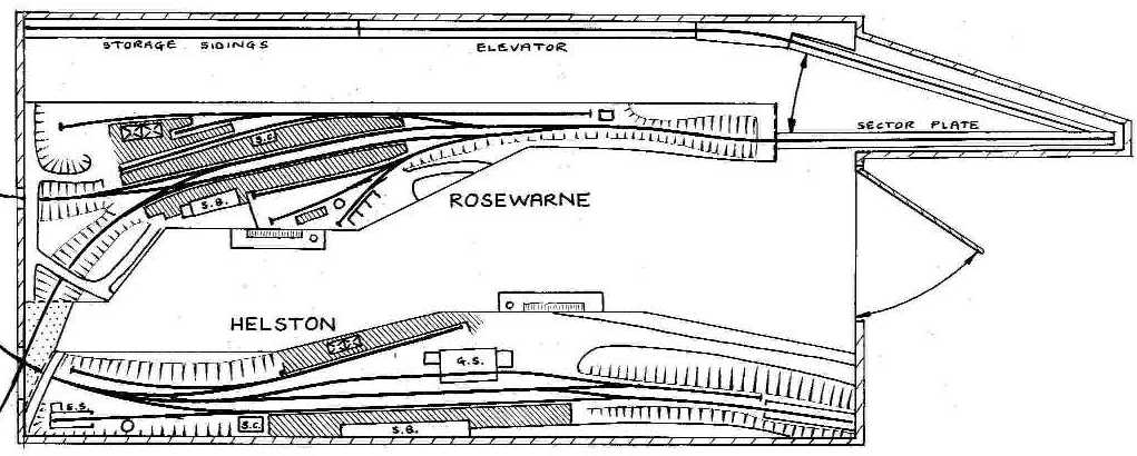
Layout Diagram – Diagram of the new layout showing the walkway at the top beyond the original Rosewarne station. The elevator and storage sidings can be seen hugging the wall at the top of the diagram, and the sector plate in its extension box is at the top-right.
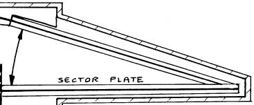
An enlarged view of the sector plate arrangement. Alignment is achieved using a bolt and electrical connection is by sprung phosphor-bronze contacts and works automatically.
The only other elevator that I can remember reading about is that designed by Rev Peter Denny shortly before his retirement when he thought he might have to resort to a two-tier layout due to space limitations. His prototype elevator (Model Railways Vol 10, Oct 1981, pp 551-553 and Peter Denny’s Buckingham Branch Lines – Part 2 1967-1993, Wild Swan, pp169-171) had two independent lifting sections for double-track operation and used many Meccano components within a wooden framework. His lateral alignment system utilised flanged wheels bearing on vertically-mounted ‘Bonds’ flat-bottom rails set at 1¾ inch gauge, allowing 4 mm scale stock to pass between the rails. The vertical alignment was by virtue of the fact that at each end of the lifting section two sets of flanged wheels were mounted in a long-wheelbase rigid ‘truck’. The hoist system used a motor to wind nylon cord onto a drum via Meccano 3-sleeve pulley blocks, and therefore needed counter-balance weights to ensure a similar load in both directions and to prevent a rapid descent in the event of failure of the drive system. I am sure that Rev Denny anticipated many of the problems that I only encountered later, but I was at least able to discuss them with him as I have been privileged to be a regular operator of Buckingham for the past twenty years. My aim was to make my elevator as simple in concept as possible.
2. The Elevator Design
The design of the elevator is the result of numerous discussions with Lyn Jones, a friend and colleague with whom I have designed many electrical and mechanical systems during the course of our work. Eventually he agreed to build the component parts for me as well (probably deciding that would at least stop me going on about it!) and made several improvements to the design during manufacture (as usual).
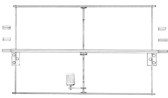
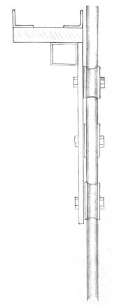
Sketch showing the basic design of the elevator with a central lead screw driven via a toothed-belt from a 240V DC motor. At the right and left-hand ends are vertical bars that provide coarse horizontal alignment. The two carriages running on these bars provide vertical alignment, keeping the lifting section horizontal.
The basic concept is to use the wall of the room to provide rigidity to the elevator and then to focus the design on smooth, reliable motion, and accurate alignment. Both horizontal and vertical alignment of each end of the elevator would have to be accurate and repeatable. We decided that the elevator design should be capable of reproducing alignment to within ± 2 mm, with conical-ended bolts providing the fine alignment.
We chose a lead-screw drive rather than a hoist in order to make the elevator fail-safe and remove the possibility of a sudden descent of precious rolling stock. Other advantages are the simplicity of the drive, as little gearing would be necessary, and hopefully there would be no need for counter-balance weights. Initially we considered two lead-screws coupled using a chain or toothed belt. This would have solved the horizontal and vertical alignment problems at both ends of the elevator but the drive system would have been more complex than necessary. As Lyn was expecting to have to turn the threads of the lead-screws on his lathe at home, he saved himself some work by suggesting the use of a single lead-screw with a bar at each end to achieve both horizontal and vertical alignment of the ends of the elevator. By using three rollers bearing on each bar he assured me that the elevator would remain level. I have to say I was sceptical, but the first time I assembled it Lyn was proved right – provided the train is balanced over the centre of the elevator it remains level and stable. The vertical bars also provide the coarse horizontal alignment for each end of the elevator.
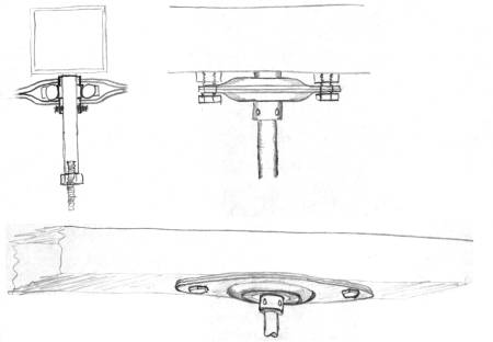
Construction The basic frame is constructed using 25 mm box section steel for the horizontals, screwed directly to the wooden wall, and 12.5 mm solid steel rod for the two vertical ends. I found it necessary to screw these two rods to the wall, in the middle of their height, to prevent horizontal misalignment of the lifting section. Subsequently I learned that it would be better to fix them directly to the storage roads as the wooden wall flexes with humidity and temperature variations.
Sketch of the method for fixing the vertical alignment rods to the horizontal box-section.
3. Transmission System
Our first attempt at a lead screw used a 2 metre long 19 mm (3/4″) diameter steel bar because we thought this key component should be made as sturdily as possible. We quickly noticed our mistake when the elevator was first assembled and tested. In the absence of a lathe large enough Lyn had threaded it by hand with a ¾ UNF 16 TPI die. Unfortunately the thread had wandered somewhat along the length of the lead screw causing a bend to develop in the bar as well as the thread no longer being coaxial with the bar. Cutting the screw thread had resulted in the lead-screw no longer being straight and, as it was more rigid than the alignment bars at each end of the elevator, the lifting section followed the eccentric oscillations of the lead screw! The result was an alignment inaccuracy of up to 5 mm and a decidedly drunken progression of the lifting section! In a sense this was a fortunate turn of events because we realised that we should use a much narrower lead-screw, with a proportionately smaller thread pitch such as commercially-available ‘studding’, thus eliminating the need to cut a thread. The narrower lead-screw would be less rigid than the end bars and hence any lack of straightness would not be transmitted to the lifting section of the elevator. We chose to use 8 mm diameter studding with a 1.25 mm thread pitch (approximately 20 TPI). This is even available in the larger DIY stores such as B&Q Warehouse.
The lead screw is terminated at each end by screwing into a short rod with a locking nut to transfer the drive. This rod fits into the bearing and, at the lower end, also goes through the drive pulley.
Sketches of the bearings at the ends of the lead screw. These bearings were just the nearest to hand but they do have the advantage of self-alignment prior to tightening.
4. Drive System
I bought a 240 V dc, 0.37 Amp motor that was discounted at a local hardware shop and we linked this to the lead-screw via a toothed belt and 2:1 reduction pulleys. The motor is rated at 1/15th horse-power and 1725 rpm but I wanted to be able to vary the speed and reverse the direction. Normal operation is at about 600 rpm for the leadscrew, or 1200 rpm for the motor. This traverses between adjacent storage roads in 10 to 20 seconds. Both the field and armature windings were available for wiring separately on this motor. Trials suggested that maximum speed control and power were obtained if the full 240 V was applied to the ‘field’ windings, whilst varying the ‘armature’ voltage to adjust the speed. The ‘field’ supply was full-wave rectified using mains-voltage diodes in a bridge rectifier circuit mounted in a 4-terminal mains junction box. A ‘switchable’ dimmer varies the ‘armature’ voltage and mains-voltage diodes were used to half-wave rectify the mains supply. These were wired into the pattress of a standard single-pole two-way light switch, one into each ‘way’ but in opposite senses, thus reversing the direction.
Circuit diagrams for the field and armature of the 240 V dc motor. Note that the armature circuit has an additional switch to break the circuit that is described below.
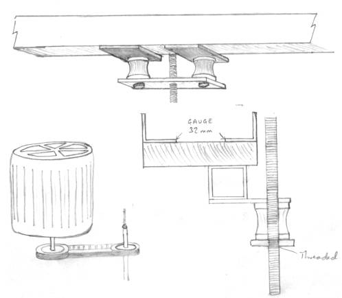
Sketches of the drive and transmission systems. The lead screw passes through a threaded hole in a plate, which is connected to the lifting section via two rubber mounts to allow relative movement.
5. Alignment and Locking
As mentioned above, Lyn’s method of using carriages at each end of the elevator that move up and down the vertical rods was intended to achieve coarse horizontal alignment as well as adequate vertical alignment of each end with the storage roads. His method required the use of three rollers on bearings. The roller design had to provide support in all directions. To achieve this it was necessary to fit a “tyre” to each bearing which accurately fitted the vertical guide rods. Lyn made these tyres from nylon and machined into them a semi-circular groove the same radius as the guide rods using a form tool (described below) made from a piece of the guide rod. While still mounted in the lathe chuck, the centre hole for the ball journal was bored into the nylon to form a press fit, this ensured that the tyre ran true. On reflection it may have been just as good to use a ‘V’ cut for the tyres.
To make the form tool, Lyn faced off a small length of guide rod in the lathe and turned a 5 degree taper to provide a concave face and sharp cutting edge. He turned a further 5 degree taper along its length, drilled an 8 mm axial hole through the middle and parted off to form a ‘button’. The button was then case hardened and bolted to a piece of square stock to complete the tool.
To further improve the stability, Lyn used double-row ball journals to mount the tyres. Two rollers had fixed mountings but the third roller’s bearing was mounted on an eccentric post allowing adjustment so that the three rollers can grip the vertical bar enough to provide the vertical alignment, but not so tightly that the carriages seize up.
This carriage system does perform the job adequately. Alignment is within the ± 2 mm requirement in most circumstances, and the bolt system provides the fine alignment. A linkage system was provided to allow the operator to throw both locking bolts simultaneously from one lever, despite the fact that they are 8 feet apart. The lever is position near the end where the operator stands to control the elevator and any shunting operations. The locking bolts are made from brass rod sliding in brass tubes that are a good fit. The ends of the bolts were turned to a cone shape in an electric drill using a file.
Diagram of the fine alignment bolts and the flat section steel linkages that allow the operator to control these by the movement of one lever. The thick lines are slots through which bolts pass to keep the flat linkages in line.
When the elevator is unbalanced by placing an ‘O’ gauge locomotive at one end of the 8-foot long lifting section, a vertical deflection of about 5 mm results. This is not a major problem but I am considering two possible improvements. One method is to install a system of crossed cables (as used in a draughtsman’s drawing board) to keep the lifting section absolutely horizontal. With a crossed-wire system the carriages could be simplified to have two rollers at the same height, one either side of the bar.
The second possible method assumes that the deviation of the lifting section from horizontal is caused by a lack of rigidity in the lifting section, dominated by the flex in the 25 mm box section connecting the three-wheeled carriages. Some modest triangulation of the cross beam or even a sheet of light alloy, say 250 mm deep by 2.4 m long and 1.5 mm thick, between the carriages would greatly enhance the rigidity.
Alignment system (left) using three rollers bearing on the vertical bars.
Two proposed crossed-wire systems for ensuring that the elevator’s lifting section remains horizontal. The lower system ensures that the wires stay clear of the drive and transmission systems.
6. Vertical Positioning
Stopping the elevator at the correct height to align with the storage roads is automated using a reed switch mounted at one end of the lifting section. The magnets that operate this reed switch are screwed to the wall in places that result in correct vertical alignment of that one end. In addition, there are magnets mounted at the upper and lower limits of vertical operation to act as safety ‘stops’. Some of these components are available, in suitable white plastic casing, as extra sensors for DIY burglar alarms.
Unfortunately the alignment can only be set up either for upwards or downwards travel because the elevator stops too soon in the other direction. I opted for alignment on upwards travel. When moving down I have to press an over-ride push-switch to over-run the magnet, reverse, and then approach the storage road level from below. It would be possible to align a second set of magnets and a reed switch for downwards motion at the other end of the elevator. The correct reed switch would need to be selected automatically based on the direction of travel.
Circuit diagram of the relay-based circuit for electrical interlocking, which allows train movements but no elevator movement when the bolts are locked in place. This requires the use of a normally-closed reed-switch or reed-relay in order to provide fail-safe operation – i.e. where the armature cannot be powered if the relay is not energised. If a normally-open reed-switch is used instead, then all switches including those on the relay should be reversed and the over-ride button (now normally-closed) will need to be in series with the reed-switch to break the circuit. This, however, would not be a fail-safe method.
A much more elegant method of positioning, which I may adopt in the future, would use one magnet and many reed switches – separate up and down switches for each storage road. Then the correct reed switch could be selected based on the desired storage road and the direction of travel.
7. Electrical Interlocking
Electrical interlocking is provided mainly to prevent damage to the elevator or rolling stock. Early experiences demonstrated the dangers of the motor starting whilst the bolts were still locking it in position – hence the slightly bowed lifting section! There is also the possibility of locomotives becoming live and running off the end of the elevator when it is not in line with a storage road.
The main interlocking is controlled by the same lever that the operator uses to throw the locking bolts. This operates a micro-switch that, via relays, disengages the elevator’s motor drive circuitry and connects the track controller to the aluminium ‘rails’ of the lifting section. All the back ‘rails’ of the storage roads and lifting section are permanently electrically connected together. Power is distributed to the front ‘rail’ from the elevator to the storage roads by the brass locking bolts. Additional copper clips are used to energise or isolate storage roads. These divide the locomotive spur roads unto two separate electrical sections to allow independent control of two locomotives in each road.
8. Operation
After a couple of running sessions I am still the only person able to operate the elevator. This is mainly because I am still trying to determine the best methods of operation and iron out the bugs. These divide into mechanical and operational issues. The mechanical problems have been caused by seasonal variations in temperature and humidity, which alter the relative positions of the storage roads and the elevator because they are fixed to a wooden wall. An improved design would extend the top and bottom box-section horizontals and include similar box-section verticals to make a complete frame. The storage roads could then be fixed to these additional vertical sections instead of to the wall. An alternative would be to use larger diameter bolts, which would be tolerant of greater misalignment.
Operational issues concern the arrival and departure of trains, controlled by an operator who can also shunt the goods yard at Rosewarne in his spare time! The nature of the switch-back style of operation is such that trains arrive on the elevator being pushed off the sector plate by the locomotive. This is convenient for shunting carriages and wagons into the storage roads, which are beyond the elevator, but can cause buffer locking on the curved exit from the sector plate. The locomotive can then be put into the locomotive spurs. However, on departure, the locomotive needs to be at the far end of the train so it would again push the train onto the sector plate. A solution requires the use of a pilot for shunting, which ends up at the other end of the train. I have installed a section break at the far end of the sector plate with an isolator switch near to the operator. The intention is to use this isolated section to store the pilot after it has pulled the train onto the sector plate. The train’s locomotive can then be attached prior to departure. This method would also ease the buffer-locking problem because the train would be pulled over the curve.
In the future I hope to have a main line garden section fed by a lower level on the same elevator. At this stage several new storage roads will be introduced above and below the present three.
9. Conclusion
All the main requirements for train operation have been satisfied by the vertical system of traverser and storage sidings. I have a railway in the specified size of shed with a walkway beyond the station and an additional station under construction on the other side of the shed.
A few improvements will be made to the mechanical alignment and electrical positioning systems as detailed above. Operationally I need to make some changes such as the use of a pilot for shunting departure trains.
We hope this article has inspired other modellers to consider moving into the vertical dimension with their storage sidings and look forward to reading how they solve the problems.
10. Photographs
Rosewarne station with the back-scene (kindly painted by my father) raised in position. This back-scene used to be fixed to the wall in the layout’s original garage location. However, it now prevents access to the goods yard from the walkway for coupling purposes.
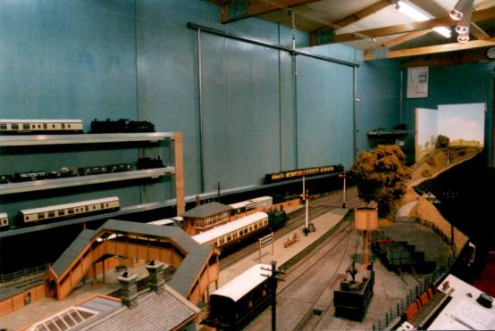
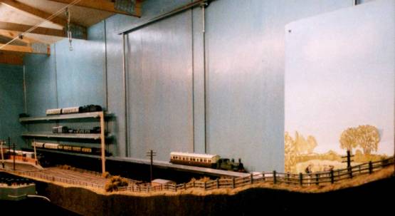
The same scene but with the back-scene lowered out of sight to allow shunting of the goods yard from the walkway. The elevator can be seen in the background attached to the wall of the railway shed. Thanks are due to my wife for suggesting that I paint the walls blue above the height of the railway and black below! Note the three main storage sidings attached to the wall on the left.
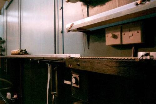
Sector plate in position to receive a train from Rosewarne. Note the entrance to the extension box on the right with a hinged flap (insulated!) that is lockable for security. Short storage sidings for locomotives can be seen attached to the wall.
Sector plate in position with an auto-train arriving from Rosewarne. Note the entrance to the extension box on the right with a hinged flap (insulated!) that is lockable for security. Short storage sidings for locomotives can be seen attached to the wall.
Sector plate moved over to the position for sending the auto-train from Rosewarne onto the elevator and into the storage sidings.
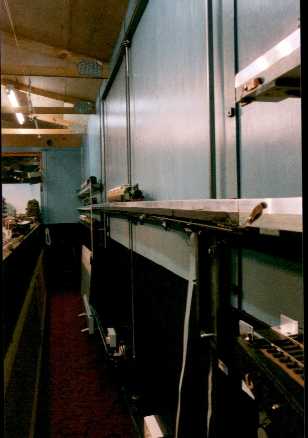
The auto-train has arrived on the elevator and is ready to be raised to the next level. Note the three main storage sidings attached to the wall in the background.
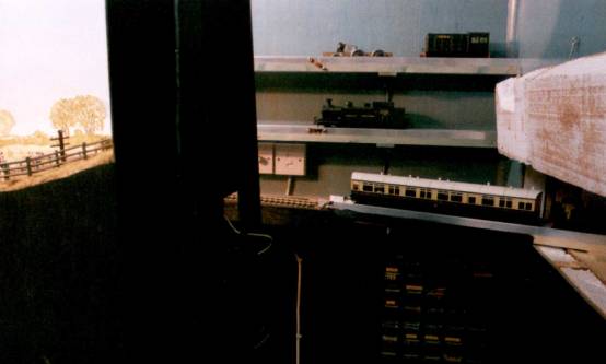
The auto-train has arrived on the elevator and is ready to be raised to the next level. On the right are the controls for the elevator – a dimmer switch for speed and a two-way light switch for direction. Below baseboard level is the controller mounted on a box containing the electrical interlocking circuitry. At the near end of the elevator, attached to the wall are the magnets that trigger the automatic stop ensuring vertical alignment.
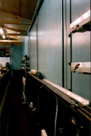
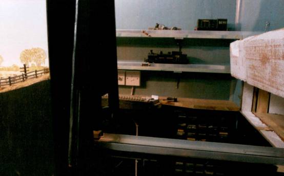
The auto-train on the elevator at the lower and middle levels. At the near end of the elevator, attached to the wall are the magnets that trigger the automatic stop ensuring vertical alignment.
The auto-train safely stored in one of the short storage sidings meant for locomotives.
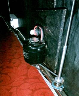
The drive (left) and transmission (right) systems showing the motor with a toothed belt to drive the lead screw and the lead screw driving the elevator using a threaded steel bar linked to the elevator using rubber linkages.

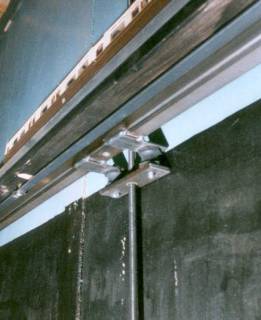
A view of the carriage at one end of the elevator. One of the wheels bearing on the vertical rod can be seen.

A view of Rosewarne station from the new walkway between the baseboards and the elevator.
© Copyright Robert A Smith, 2005-19